Model Aircraft Power System Selection Using Your ComputerA Tutorial Introduction to MotoCalcStefan Vorkoetter |
Introduction
The biggest obstacle facing both the new and experienced electric R/C aircraft hobbyist is the selection of an appropriate power system. In the early days of electric flight, the difficulty arose from the limited availability of suitable motors and batteries, requiring careful optimization in order to get something to work at all. That has changed, but there are now so many choices covering a wide range of aircraft from indoor to quarter-scale. The problem now is one of choosing the appropriate components from the many available to best power one's aircraft.
MotoCalc was designed to automate much of this process. In 1997, it helped in designing optimal power systems using the few components available. Today, it does this and much more for the modeler faced with an overwhelmingly large selection of components. This article examines the problem of electric R/C airplane power system selection, and how to effectively use MotoCalc to solve it without the expense of a trial-and-error approach.
Power System Selection Overview
Selecting the appropriate motor, propeller, and battery for an electric
powered model airplane can make all the difference between a model that will
not fly, and one with stellar performance. Choosing the correct power system
is not trivial, and must take into account the desired performance and the
specifications of the airframe.
Why Is It So Difficult?
|
|
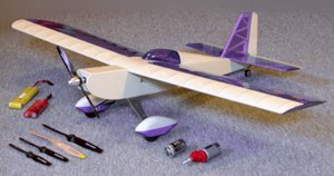
| Choosing from the many possibilities can make electric power system selection difficult. |
Similarly, the decision of which propeller to use is an almost automatic consequence of the choice of engine. Internal combustion engines are maximally efficient over a very narrow range of RPM, meaning that there is a very small selection of suitable propellers. One simply uses one of the propellers recommended by the engine manufacturer. Using too large a propeller will bog down the engine. Too small and the engine will over rev.
An electric motor has a much wider performance range. One motor can be used with many sizes of propeller. Larger propellers will cause the motor to draw more current and produce more power (to a point). Smaller propellers will draw less current, and produce more RPM. The same motor can be used with a small high-pitch propeller for a pylon racer, or a larger low-pitch propeller for a sailplane.
Because of the smooth running characteristics of electric motors, it is also easy to attach an inexpensive and lightweight gearbox, trading RPM for torque. This further expands the range of usable propellers, and hence the range of aircraft for which the motor is suitable.
Finally, there is the battery. This has often been compared with the glow model's fuel tank, but that is a woefully inadequate analogy. The size of a fuel tank determines how long the engine will be supplied with fuel. The size of the battery determines this and many other factors. Using a larger battery may increase running time. Or, it may decrease running time while increasing the power available. The exact effect depends on the motor and propeller used as much as it depends on the battery.
In short, the power system for an electric plane must be chosen as a
system. One cannot choose a motor, propeller, battery, and possibly a
gearbox in isolation. Because every choice of component affects the possible
choices for other components, this can be a difficult and time consuming
process. MotoCalc can do most or all of this work automatically,
producing suggestions for complete power systems, predicting their
performance, and allowing "what-if" analysis to optimize them further.
Setting Performance Goals
The first step in choosing a model's power system is to know what the plane is intended to do. The performance expected of a trainer is very different than that of a pylon racer. If we are flying 3D aerobatics, we will have very different requirements than those of an electrically launched Sunday afternoon sailplane.
There are two main aspects of performance: the type of flying we intend to
do, and how long we want to do it in one sitting. More aggressive flying
requires more power. Longer flying requires more battery capacity. These two
aspects of performance are at odds with one another, since more power means
more drain on the battery, resulting in shorter flying times. Optimizing a
power system to balance these two requirements can be a significant
challenge.
Understanding the Aircraft
The characteristics of the aircraft play a large role in how it can and will fly. The most significant factors are weight, wing area, wing span, and airfoil (wing cross-section) shape. Higher weights require higher speeds or more wing area in order to remain airborne. Short stubby wings have more drag but are more maneuverable than long slender wings. Symmetrical airfoils fly as well upside-down as right-side-up, but require some up-elevator to maintain level flight. Thick wings provide more lift than thinner wings, but suffer from high drag at higher flying speeds.
It is important to choose an aircraft suitable for the sort of flying we want to do. A two-meter sailplane will not make a good 3D aerobat no matter how good a power system we put in it. A pylon racer won't be good for soaring regardless of how light it might be and how fast it can climb to altitude.
The aircraft's characteristics also influence the sort of power system that
can be used. A large lightweight model can carry a heavier motor and battery
than a similarly sized model that is heavy to begin with. A model with a
large wing span can use a larger propeller without being adversely affected
by propeller torque or looking out of proportion.
Determining Power Requirements
Regardless of the motor, battery, and propeller eventually chosen, any airplane needs a certain amount of power to achieve a desired level of performance. One simply cannot get around the laws of physics. Because of this basic fact, a number of "rules of thumb" have been proposed based on a plane's power to weight ratio. For example, it is suggested that a plane have about 40 to 60 Watts of power per pound (88 to 132 W/kg) of aircraft for typical "sport" type flying. More aggressive aerobatic flying requires about 70 to 100 Watts per pound (154 to 220 W/kg).
Unfortunately, adequate power alone does not guarantee success. It is quite possible to put a 100 Watt power system in a one pound (450 g) airplane and still be unable to take-off. Or, the plane may be able to hover and climb vertically, but not fly horizontally fast enough to remain airborne.
The power that moves an airplane is the product of two things: thrust and
speed. The selected power system must provide these in the correct
proportions if the plane is to be able to fly as intended. Too much speed
and too little thrust can produce a plane that theoretically flies well at
high speed, but is unable to accelerate to that speed in the first place.
The opposite case will give that nice vertical climb without the ability to
actually fly like an airplane.
Selecting Power System Components
The goal then is to choose power system components that work together to provide the power we need, in the form that we need it (thrust vs. speed), for the type and duration of flying we want to do. There are literally billions of possible combinations of power system components, the vast majority of which are unsuitable for the task at hand. The trick is to find the right combinations.
More often than not, the selection process is hampered by other factors such as price and availability. This requires substitutions of other components for the ideal ones, which in turn affects the choices of the remaining parts of the power system.
Using MotoCalc for Power System Selection
|
|
|
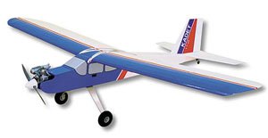
Sig's Kadet LT-25 glow trainer is an ideal candidate for conversion to an electric trainer. Photo courtesy of Sig Manufacturing.
www.SigMfg.com |
MotoCalc's usefulness does not end once a power system has been selected. For instance, the ability to produce a wiring diagram eases the wiring of complex multi-motored models. After test flying, if the model is found to be deficient in some area, further "what-if" analysis can be done in MotoCalc to determine how to improve things most effectively.
In the rest of this article, we will examine the use of MotoCalc in
selecting, analyzing, and optimizing an electric power system for a specific
aircraft, the Sig Kadet LT-25, a popular .25 sized glow powered
model. In glow powered form, this model has the following specifications:
| Wing Span: | 63 in (160 cm) |
| Wing Area: | 724 sq.in (46.7 dm2) |
| Weight: | 4 to 4¼ lb (1.36 to 1.93 kg) |
| Wing Loading: | 12 to 13 oz/sq.ft (29 to 41 g/dm2) |
The MotoWizard Provides a Starting Point
For the beginning electric modeler, the MotoWizard is the place to start. Using the MotoWizard requires virtually no knowledge of motors, batteries, propellers, and gearboxes. All one has to do is enter some information about the aircraft, desired level of performance, and approximate elevation above sea level, and the MotoWizard will do the rest.
When MotoCalc is launched for the first time, the MotoWizard will be displayed automatically. (If you have turned off this feature, click the "wizard hat" icon, select MotoWizard from the Project menu, or press Ctrl+W.)
The MotoWizard has ten pages, accessed by clicking on the tabs across the top. The Wizard will also proceed to the next page in sequence if one clicks the Next button or presses Alt+N. The first page looks like this:
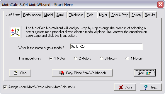
The model name that appears will be that of the project last worked on in MotoCalc. Since we want to run the Wizard on a new aircraft, we'll click the Clear button, type in the name of the aircraft, and select the number of motors that it is to use. Since the LT-25 is a single-motor plane, we've selected 1 Motor.
Clicking the Performance tab or the Next button brings up the Performance page:
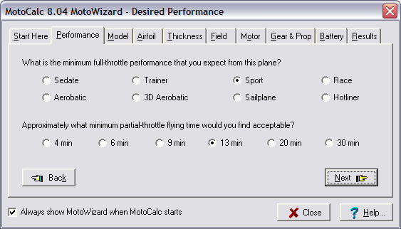
Here is where we'll tell the MotoWizard what type of flying we wish to do with this model, and what typical flight times we expect. The LT-25 is designed to be a trainer, but it also makes a good sport model. And, since we would like to have flight times equivalent to its glow-powered cousins, we've selected Sport and 13 minutes as our goal. The Sport setting allows for some aerobatics, without the unlimited vertical that Aerobatic implies, or the hovering ability inherent in 3D Aerobatic models.
Clicking the Model tab or Next button takes us to the Model page:
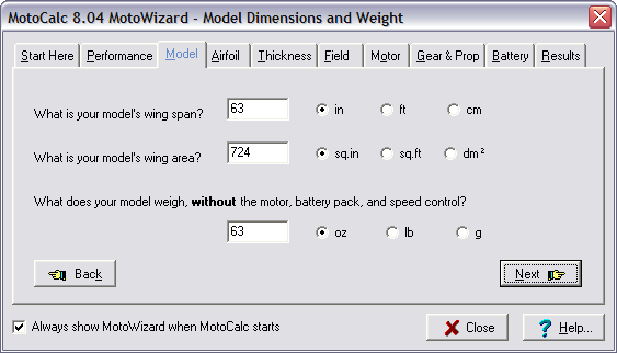
The Model page is used to enter the basic specifications of the model: wing span, wing area, and empty weight. We'll type the correct value into each of the three data boxes and select the appropriate units. It is important to enter the weight of the model not including the weight of the motor and gearbox, motor battery, and speed control. This is because the ready-to-fly weight will depend on the particular power system components selected, and these are not known yet. MotoCalc will automatically add on these additional weights as it evaluates potential power systems.
If we don't know the empty weight (e.g. you haven't purchased the model yet, or haven't built it), we can make a good guess. For a glow powered model, this is the published flying weight minus an estimate of the engine weight. Most glow engines weight about 20 ounces per cubic inch of displacement. For example, a typical .40 engine weighs about 8 ounces.
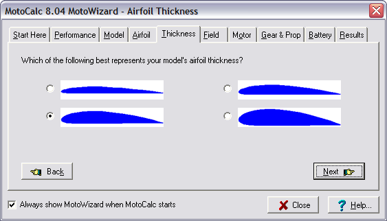
The next two pages of the MotoWizard are used to specify information about the model's airfoil. Don't worry, because all that is required is the approximate shape and thickness. We select the shape on the Airfoil page:
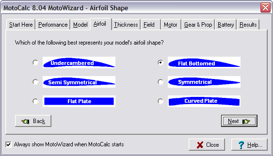
The thickness is selected on the Thickness page. On both of these airfoil information pages, we just need to choose the picture that most closely resembles the model's airfoil. The LT-25 has a medium thickness flat-bottomed airfoil:
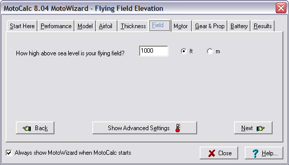
We're now done telling the MotoWizard about our model. One more piece of information is needed before the Wizard can begin to think about possible power systems, and that is the approximate elevation of our flying field. The air is thinner at higher altitudes, and although this does not affect a motor or battery directly, it does affect the propeller, and the speed at which the plane must fly to remain airborne. The easiest way to find out our approximate elevation is to call the nearest airport. Clicking on the Field tab or Next button takes us to the Field page, where we can enter the elevation:
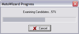
The next three pages, Motor, Gear & Prop, and Battery are where we can choose to restrict the MotoWizard to specific types or brands of motors, gear ratios, propeller sizes, and batteries. For now, we'll skip these pages and go straight to the Results page by clicking the Results tab. You will see a progress indicator like this:
After a few seconds, depending on the speed of the computer and the number of plausible power systems for the model, the Results page will appear:
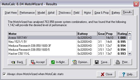
At the top of the Results page is a brief summary of what the MotoWizard has done. In this example, it has looked at over three-quarters of a million possible power systems for the LT-25 in detail, and narrowed it down to just over a thousand good choices.
The choices are presented in a table showing the suggested motor, battery, gear ratio, propeller size, and a rating. The motors can be any of the motors in MotoCalc's database for which the weight is known (all modern motors, and most older motors too).
The Battery column shows the suggested battery. Unlike motors, the MotoWizard only looks at a small number of possible cell types, chosen to be typical of the types available. It combines these into batteries of varying numbers of series- and parallel-wired cells. Each entry in the table is of the form NNxTTTT-MMP, where NN is the number of series cells, TTTT is an abbreviation of the cell type, and MM is the number of parallel cells. If the cells aren't paralleled (i.e. "1P"), that part of the designation is omitted.
The recommended gear ratio is shown in the Gear column. Here again, the MotoWizard doesn't consider specific gear boxes, but only gear ratios. Any suitable gearbox with close to the suggested gear ratio can be used. For direct drive power systems, the MotoWizard leaves the Gear column blank.
The Prop column shows the suggested propeller size. Like the gear ratio, these are generic sizes of no particular brand. The format is DDxPP, where DD is the diameter and PP is the pitch. Both are measured in either inches or centimetres, depending on whether you've configured MotoCalc for Imperial/US or Metric measures.
The last column is the Rating, which gives a figure of relative merit for
each of the suggested power systems. Please do not think of this as a
percentage. For example, a rating of 0.5 is not only half as good as a
rating of 1.0. Furthermore, the rating numbers from one run of the
MotoWizard cannot be meaningfully compared to those of a different
run. All of the suggestions displayed by the Wizard are the best ones
it could find; the ratings just show which are the best-of-the-best.
Narrowing Down the Choices
The results above show huge number of choices, but this is to be expected
when the MotoWizard is given completely free rein. Fortunately, it's
fairly easy to narrow down the choices using the Motor, Gear & Prop, and
Battery pages we skipped over before. We'll start with the Motor page, by
clicking on the Motor tab.
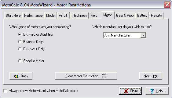
The options on the left side of this page let us choose the category of motor we want to use. By default, any brushed or brushless motor will be considered. We can specify Brushed Only or Brushless Only to narrow down the choices.
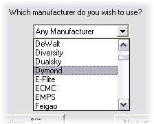
On the right side of the page, we can select a specific manufacturer to further restrict the choices to that manufacturer's motors.
If we choose Specific Motor in the options on the left side of the page, then the right side changes from a manufacturer selection to a specific motor selection:
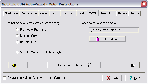
For the LT-25 that we're using as an example, let's choose the Brushless Only option, and choose Model Motors (makers of the popular AXI motors) as the preferred manufacturer. Returning to the Results page produces the following:
Notice that there are now far fewer power systems that were tried, and also far fewer that were finally suggested. We'll now go to the Gear & Prop page to narrow things down further:
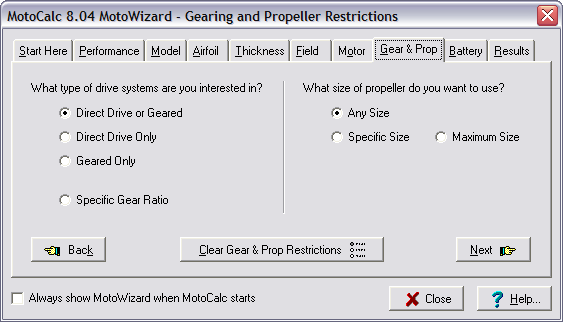
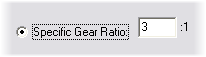
The left side of the page is used to narrow down the gearing choices, just like the left side of the Motor page was used to narrow down the types of motors. Choosing Direct Drive Only, the MotoWizard will not consider any geared power systems. Conversely, selecting Geared Only will produce only power systems with gearboxes. Finally, the Specific Gear Ratio choice opens a field where we can type in a precise gear ratio (for example, to make use of a gearbox we have on hand):
Since we've already specified that we want to use Model Motors' AXI series of motors and these are all outrunners, we'll select Direct Drive Only (as one does not usually use gearboxes with outrunners).
On the right side of the page are options for propellers. By default, Any Size of propeller is considered. We can also give a Specific Size (to look right on a scale model for example), or a Maximum Size. If we choose either of these options, two fields appear where we can type in the specific or maximum pitch and/or diameter:
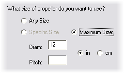
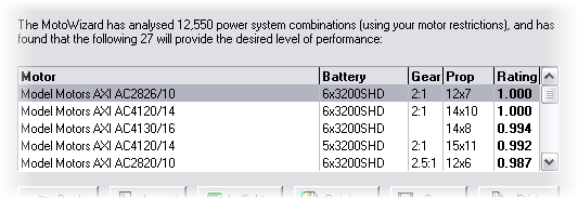
For our LT-25, we'll specify a Maximum Size of 12 inches in diameter to ensure adequate ground clearance. Leaving the Pitch field blank leaves the MotoWizard free to choose an appropriate pitch. Returning once again to the Results page, we now have:
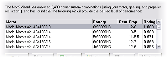
Notice that the Wizard has considered fewer power systems (2,498 versus 12,550 previously), but has produced more results (42 versus 27). This can happen when a restriction you impose (direct-drive and a maximum propeller size in this case) causes the MotoWizard to consider systems it might otherwise not have "thought" of.
Of the forty-two suggested power systems, twenty-four use high output lithium polymer (LiPo) cells and eighteen use nickel metal hydride (NiMH) cells. Using the options on the Battery page, it is possible to tell the MotoWizard to restrict its choices to a specific type or types of cells:
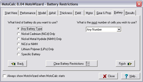
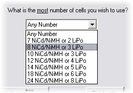
The options on the left side work much the same way as those on the left side of the Motor and Gear & Prop pages. When any one of the first five kinds of battery is selected, the right side of the pages lets us specify a maximum cell count:
If we choose Specific Battery on the left side of the page, the right side changes to let us choose a specific cell type and the exact number of series and/or parallel wired cells. Like the propeller pitch and diameter fields, leaving either of these fields blank leaves the MotoWizard free to choose appropriate numbers. We can also leave both fields blank, thus specifying only the type of cells to use, but not the number.
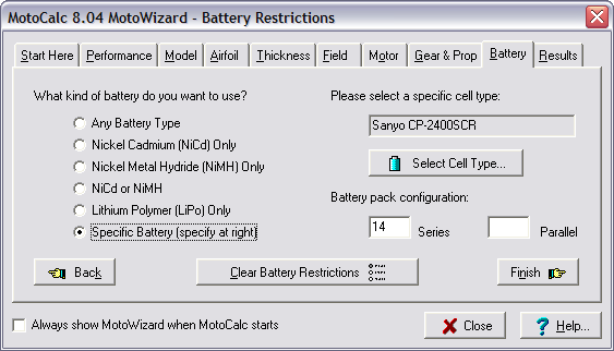
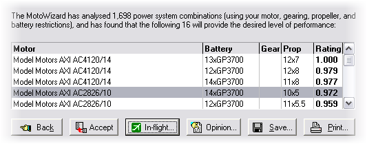
For our LT-25, let's set the left side to NiCd or NiMH because we have plenty of these on hand and don't want to go out and buy new LiPo packs and a charger. And, we'll select 14 NiCd/NiMH as the maximum number of cells to use. This gives the following Results:
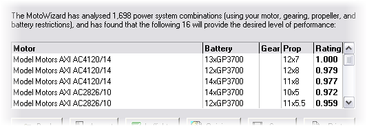
We've now narrowed our choices down to sixteen. If we have a lot of seven-cell NiMH battery packs on hand, the third choice is ideal, because we can use two packs in series instead of having to construct a custom large pack.
The next step is to copy the desired power system to the
MotoCalc Workbench to do a more detailed
analysis, and possibly substitute components. To do this, we click on the
desired result and then click the Accept button (just double-clicking on the
result works too).
When the MotoWizard Can't Find Anything
Sometimes, the MotoWizard will be unable to find any suitable power systems. For example, if we ask for something really difficult to achieve, like 30 minutes of 3D aerobatics using NiCd cells, the Wizard will try really hard, and finally give up with a message like this:
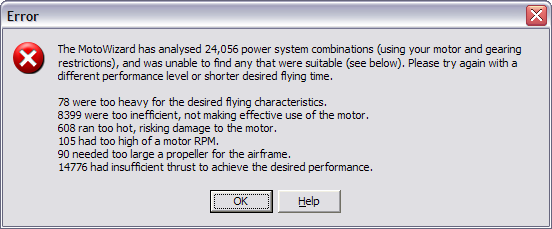
In some cases, this message means that it is extremely unlikely that the desired level of performance is possible. For example, if you have selected Sedate performance but the empty airframe is very heavy, it may not be possible for the ready-to-fly weight to be light enough for Sedate flying.
There are times however where several viable power systems exist but the
MotoWizard is simply unable to find them. Out of necessity, the
Wizard uses heuristics to narrow down the choices to at most a few
million out of the trillions of possibilities before examining those in
detail. If it were to examine every possibility in detail, the
process could take weeks or months.
The MotoCalc Workbench Performs a Complete Analysis
The Workbench is the heart of MotoCalc. This is where we can perform a complete analysis of a selected power system (either one selected by the MotoWizard, or one we've chosen ourselves). But, the Workbench does more than this. In addition to predicting voltage, current, power, RPM, and other factors of power system performance, the Workbench will predict the performance of our plane using this power system.
By selecting different motors, batteries, propellers, and gear ratios, we can use the Workbench to fine tune a power system. We can even generate predictions for several similar power systems at once, differing only in number of cells, propeller pitch, diameter, or gear ratio.
The MotoCalc Workbench will look like this after we've Accepted a power system suggested by the MotoWizard:
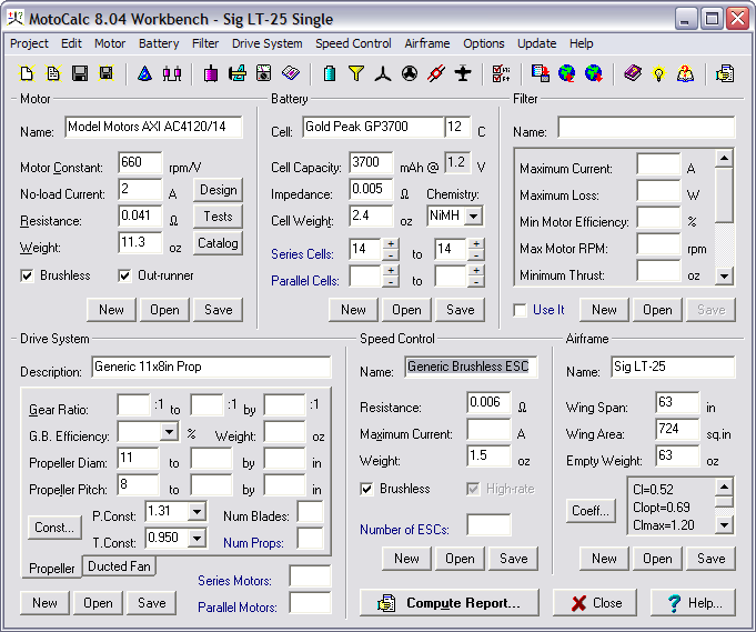
The Workbench is divided into six main sections: Motor, Battery, Filter, Drive System, Speed Control, and Airframe. Each of these except Filter corresponds to one aspect of the completed airplane. We'll look at the Filter section a bit later.
For now, let's not worry about all the information on the Workbench, and just use the data that the MotoWizard has already filled in for us. Clicking the Compute Report button tells MotoCalc to make a detailed performance prediction. This will produce an In-flight Analysis, which looks like this:
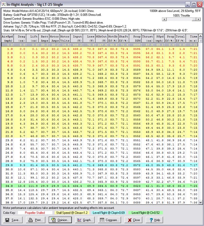
This report shows virtually everything there is to know about the performance of this power system and airframe combination. The top of the report window summarizes the power system and its overall performance. The lines of most interest are the last two, Airframe and Stats:
-
The Airframe line shows you the wing area (as we entered it), but it also shows the ready-to-fly weight ("109.4oz RTF") and the wing loading ("21.8oz/sq.ft"). The remaining information ("Cd=0.063; ...") is detailed aerodynamic data which we can ignore unless this is of interest to us.
-
The Stats line gives a lot of useful information, starting with the input and output power loading ("64 W/lb in; 54 W/lb out"). The input power loading is the figure often referred to in the Watts-per-pound rule of thumb, and 64 W/lb is more than adequate for sport flying.
-
Next we have the stall speed ("22mph stall"). This is the speed below which the aircraft will not fly.
-
After this is the optimal flying speed, required throttle, duration, and predicted motor temperature ("29mph opt @ 58% (33:11, 85°F)"). Technically, optimal flying speed is defined as flight at the speed and power level giving the longest duration (for you full-scale pilots, this is the "best endurance" speed). It's not necessarily much fun to fly at that speed, but it is a good figure for comparison. The information shown for our LT-25 gives an optimal speed of 29mph at a 58% throttle setting, giving a duration of about 33 minutes, with a resulting motor temperature of 85°F.
-
Next is the level flight speed. MotoCalc defines this as the speed at which the plane will maintain level flight with a neutral elevator setting. For our LT-25, this is 34mph at 63% throttle, with an endurance of 28 minutes. The motor will reach 88°F during such a flight. This may seem like an unusually long endurance, but keep in mind that this is only achievable if we launch into level flight, never climb, and never turn. Again, it is a useful figure for comparison, not an absolute prediction of performance.
-
Finally, we have two more figures giving the maximum rate of climb and the angle of climb at which that is reached, and the corresponding figures for minimum rate of descent in a glide.
|
|
| Comprehensive on-line help is available at the touch of a button. |
For detailed explanations of all the report columns, we can click the
Help button at the bottom of the report window, or press the F1 key.
MotoCalc has very comprehensive on-line help available throughout the
system, just a click or keypress away.
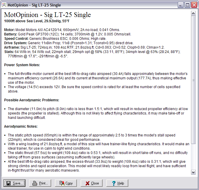
MotOpinion Explains the Results
Advanced users love the detailed analysis MotoCalc produces, but the
beginner may find all the numbers overwhelming and not very informative.
This is where the MotOpinion feature comes in. If we click the
Opinion button at the bottom of the report, we'll see a plain English
write-up of what it all means:
Comparing Different Power Choices
Often we'll want to compare more than one possible power system for a model. The easiest way to do this is using the Comparison window. By clicking the Compare button at the bottom of the report, the Comparison window is opened, and the current power system is added to it:
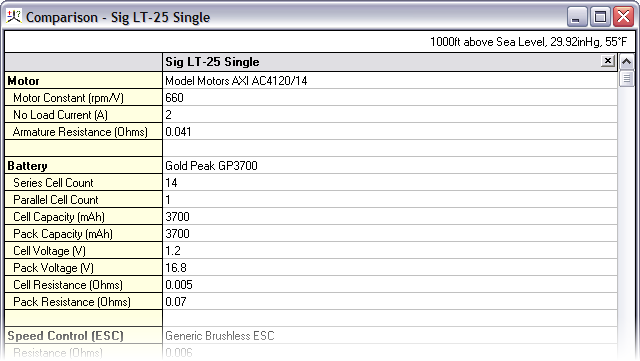
Of course, with only one power system, the Comparison is not very interesting as there's nothing to compare. Let's return to the MotoWizard Results page (just click the "wizard hat" button or select MotoWizard from the Project menu) and select a different power system that uses a different motor and propeller, but the same 14-cell battery:
To save time, clicking the In-flight button will copy the selected power system onto the MotoCalc Workbench and then proceed directly to the In-flight Analysis. Just click Compare on the bottom of that report, and it will be added to the Comparison window:
Notice that there are now two columns in the Comparison window, and that some of the rows have a light blue background shading. Each column corresponds to one of the power systems, and the shading indicates where there are differences between the columns.
We can continue to add power systems to the Comparison window in the same
way, up to a maximum of ten columns. Clicking the X in the top right corner
of a column removes that column from the comparison. Columns can also be
dragged around to rearrange them, a feature familiar to spreadsheet users.
Fine Tuning a Power System on the MotoCalc Workbench
So far, we've used the MotoWizard to automatically choose some possible power systems for our Sig Kadet LT-25, the MotoCalc Workbench to analyze them, the MotOpinion report to understand them, and the Comparison window to compare them. Now, some fine tuning is in order.
Let's start with the second power system we selected (AXI AC2826/10 motor
and 10x5 propeller). If this system isn't already on the Workbench
select it on the MotoWizard Results page and click Accept.
|
|
The MotoWizard does all its calculations and power system selection using "generic" propellers (i.e. no particular brand or style). For our model, we'll want to use a real propeller. A good choice for electric models are the electric flight propellers made by APC, so we'll use one of those. Also, let's try both 10x5 and 10x7 propellers. We'll make the following changes to the fields in this section:
- Change the Description to "APC 10x5 and 10x7 Electric Props".
- In the "to" and "by" parts of the Propeller Pitch field, type "7" and "2" respectively.
- Select "APC Electric Average" from the drop down list in the P.Const field. This will change the number in that field to 1.17.
- Select "APC" from the list in the T.Const field. This will change the number in that field to 1.
Finally, we click the Save button (at the bottom of the Drive System
section). This will save these propellers into the database so we can
retrieve them later for further experimentation.
|
|
MotoCalc's database comes pre-filled with a large number of commonly
used speed controls, so all we have to do is click the Open button at the
bottom of the Speed Control section, and select the "Castle Creations
Phoenix 45" from the list of available controls.
After making these changes, we'll click the Compute Report button again to perform an analysis. This time we get a different kind of report, a Static Analysis:
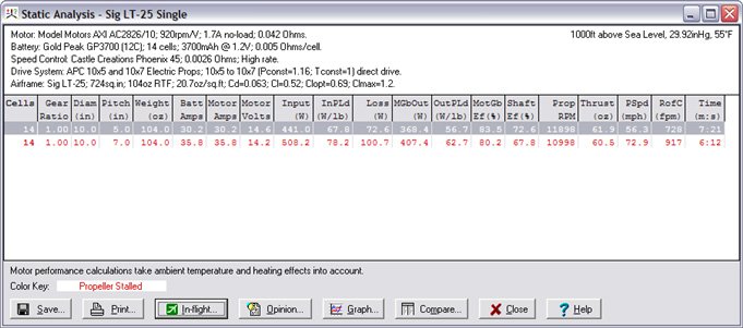
This report is very similar to the in-flight analysis, except that all calculations are done for zero airspeed (static) conditions. The reason we did not receive an in-flight analysis is because we indicated that we wanted to try two different propeller sizes. So, this report has one line for each propeller size. We can get a separate In-flight Analysis for each line in the Static Analysis by selecting that line and clicking the In-flight button (or, by double-clicking on the line).
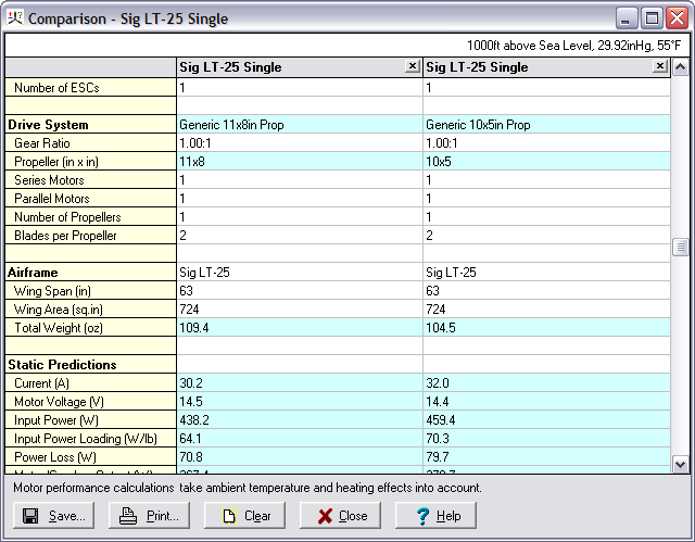
Similarly, clicking the Opinion button brings up a MotOpinion report corresponding to the selected line, and the Compare button adds an appropriate entry to the Comparison window. Let's do that for both lines in the report, selecting each line and click the Compare button. We'll also delete the first column from the Comparison window (the one with the AC4120/14 motor). The Comparison window now looks like this:
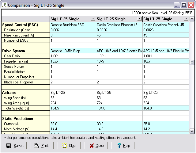
Notice that the current is lower for the APC 10x5 than for the generic 10x5
propeller. This is because of its above average efficiency. The current for
the 10x7 propeller is signficantly higher. Going back to the Static Analysis
window and asking for a MotOpinion report on each of the two
propeller options, we conclude that the APC 10x5 is the better choice.
Using Graphs to Aid Understanding
A picture is worth a thousand words, and probably at least that many numbers. MotoCalc features an extensive graphing facility to help in visualizing different aspects of power system and aircraft performance. There are literally thousands of different graphs that can be generated, so we'll only touch on a few of them here.
We'll start by returning to the Static Analysis, selecting the first line of the report, and clicking the In-flight button. Clicking the Graph button at the bottom of the resulting In-flight Analysis will produce a Graph window like this:
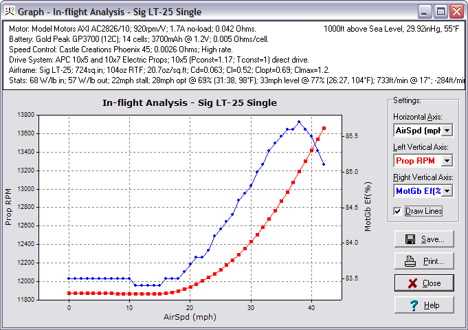
The top of the graph window merely repeats for convenience the information that appeared at the top of the In-flight Analysis window. Most of the window is taken up by the graph itself. Along the bottom of the graph are the values for the parameter we're plotting against (Air Speed by default). The left side gives values for the first parameter we're graphing (red), and the right side the values of the second parameter (blue). By default, these are Prop RPM and Efficiency respectively. (You may see a different graph if you've previously used MotoCalc's graphing, because it remembers your settings from last time.)
In the graph above, we can see that efficiency ranges from about 83.5% at low airspeeds to almost 86% at flying speed. With a less efficient motor, or one poorly suited to the model, we might see a wider range of efficiencies. The propeller RPM starts out at about 11830 at zero airspeed, drops a bit as speed increases, and then increases rapidly after about 20mph.
At the ride side of the window is the Settings section. Here we can choose the parameters we want to graph. For example, if we change the Left Vertical Axis field to Motor Amps, the graph will look like this:
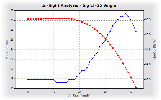
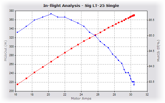
We'll use the following settings for one more example:
- Horizontal Axis: Motor Amps
- Left Vertical Axis: MGbOut (W)
- Right Vertical Axis: MotGb Ef(%)
The two vertical axes will show motor output power and motor efficiency respectively (the "Gb" stands for gearbox, because these values include gearbox losses if a gearbox is being used). These values are being plotted against Motor Amps, so the graph shows at a glance that the maximum efficiency for this motor with 14 NiMH cells occurs at just over 20 Amps, and that the maximum output power occurs somewhere past 31 Amps (the graph doesn't go further than this because the motor will never exceed 31 Amps with the battery, propeller, and airframe we've teamed it up with).
There are many more possible graphs that MotoCalc can produce from an In-flight Analysis. We can select any column of the report for any axis of the graph.
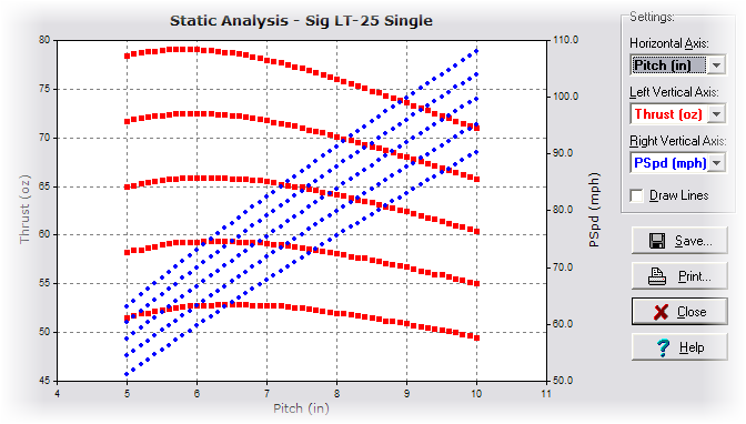
Graphs can also be generated from the Static Analysis, which is primarily useful when producing simultaneous predictions for many cell-count / propeller-size / gear-ratio combinations. For example, the following graph shows static thrust and pitch speed against propeller pitch (ranging from 5" to 10" in steps of 0.1"), for batteries ranging from 12 to 16 cells:
Produce a Wiring Diagram with the Wiring Wizard
A single-motored model like the Kadet LT-25 is quite simple to wire, but multi-motored models, for which electric power is especially well suited, can be more of a challenge. MotoCalc's Wiring Wizard takes the guesswork out of it. To illustrate this, let's return to the MotoWizard, navigate to the Start Here page, and select the 3 Motors option. Then we'll go to the Results page, select the first recommended power system, and click the Accept button.
Back on the MotoCalc Workbench, we can open the Wiring Wizard by clicking on its button (the one to the right of the "wizard hat"), or selecting Wiring Wizard from the Project menu. A diagram like the one below will appear (if you see a "Not Possible!" message, make sure the Number of ESCs field on the Workbench is set to 3).
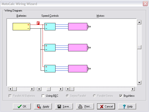
The red
" F "
represents the fuse. You can experiment with wiring diagrams for more
complex configurations (up to 6 parallel batteries, 6 speed controls, 24
motors, with and without BEC) by adjusting the sliders and check boxes in
the Wiring Wizard window.
Keeping MotoCalc Up to Date
New motors are being introduced almost daily, and new cells and speed controls almost as often. Capable Computing, the makers of MotoCalc add new data to MotoCalc's database on a regular basis, and it's easy to add this data to an existing copy of MotoCalc. Just select Update All from the Update menu of the MotoCalc Workbench. MotoCalc will then automatically connect to Capable Computing's web server and download the latest data into the database.
Sometimes new motors become available before reliable data for them is published. Often, experienced hobbyists will purchase these motors, perform their own tests on them, and share the data using MotoCalc's data contribution feature. Selecting Get Contributed Data from the Update menu presents a list of user-contributed data, with a checkbox beside each item:
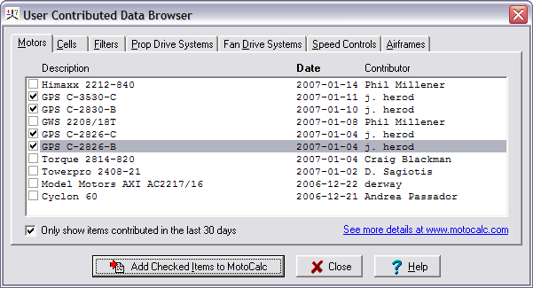
Checking off the desired items and clicking the Add Checked Items to
MotoCalc button will download those items into the database.
Advanced Features of MotoCalc
So far we've just touched on the basics of how to select and analyze an
electric flight power system using MotoCalc. As you become more
familiar with the program, you'll discover its many advanced features. Here
are brief introductions to just a few of them.
Use Filters to Narrow Your Choices
|
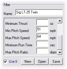
|
Because MotoCalc can generate a Static Analysis for many power system combinations at once, the Filter section is useful for removing those setups that don't meet certain criteria, such as the pitch speed rule above.
For example, if you've entered a range of propeller diameters going from 9
to 12 inches, pitch going from 5 to 10 inches, and number of cells ranging
from 10 to 16, MotoCalc would produce a Static Analysis for 168
different setups. By setting a Filter to restrict pitch speed to the range
of 51 to 64mph, thrust at least 35oz, and full throttle run time at least
300 seconds (5 minutes), the number of setups is reduced to 9, which can
then be analyzed in more detail (e.g. producing an In-flight Analysis or a
MotOpinion report).
Using Detailed Airframe Information
The MotoWizard asks for just a few basic pieces of information about your plane: weight, wing area, wing span, and approximate airfoil. For a more accurate analysis, the MotoCalc Workbench lets you specify much more detail. Clicking the Coeff button in the Airframe section of the Workbench opens this window:
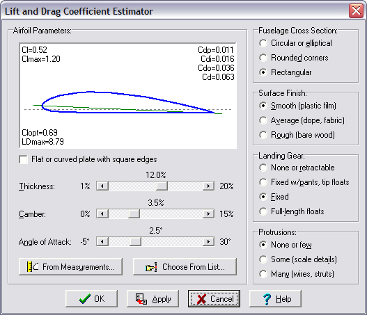
Here you can give MotoCalc a better idea of your model's airfoil, either by entering the parameters directly using the sliders, from measurements taken from the model or plans, or from a list of common airfoils.
The options at the right side of this window are used to tell
MotoCalc about the factors influencing the drag of your model (which
affects top speed, best rate and angle of climb, endurance, and so on).
Motor Parameter Determination
If you like to buy the latest motors, for which data is often unavailable, or if you enjoy building or modifying your own motors, you will want to be able to determine the motor parameters so that you can use MotoCalc to make predictions about these motors.
|
|
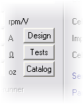
- The Design button opens a window where you can calculate the effects of changing the windings of a motor. Given one motor whose parameters and number of windings are known, this window will predict the parameters for a second motor that is identical except for the number of windings.
- To determine motor parameters from motor bench tests, click the Test button. This will open a window where you can enter two data points for which you've measured voltage, current, and RPM. You have a choice of providing free-running and under-load data, or best-efficiency and one other data point. The latter choice is useful if you have dyno data for your motor.
- Finally, the Catalog button opens a window where you can enter everything you might find about a motor in a supplier's catalog. If possible, MotoCalc will then determine motor constants from this.
Propeller Parameter Determination
When we tuned the power system for the Sig Kadet LT-25, one of the first things we did was select new values for the P.Const and T.Const fields in the Drive System section of the MotoCalc Workbench. The drop-down lists for these fields contain many popular ranges of propellers, but if you have a propeller that isn't on this list, it's possible to determine these constants yourself. This will require an accurate thrust measuring stand along with the ability to measure voltage, current, and RPM. You'll also need a motor whose parameters are precisely known.
Just click the Const button in the Drive System section of the
Workbench to open the Propeller Constant Estimator, and enter the
test data. With this information, MotoCalc can estimate thrust and
power constant values for the propeller being tested.
Accounting for the Effects of Heating
MotoCalc has many options to let you customize it to your preferences, such as the units of measurement you prefer (US, metric, or a mixture), and which columns to display on the Static and In-flight Analysis. One option tells MotoCalc whether or not you want it to take into account the effects of motor heating on motor performance.
All motors waste some percentage of their input power in the form of heat (the Loss column on the Analysis reports). As the motor runs, it gets warmer until it reaches equilibrium, which is the temperature at which it transfers heat to the atmosphere as fast as it generates more. MotoCalc can estimate this steady-state temperature, and adjust the motor parameters during the calculation to reflect the changes caused by the high temperatures.
Why might you not want to do this? In aircraft where the motor is
only run for short periods of time, or is usually run at low throttle
levels, it will never get that hot. The same is true when test running a
motor for brief periods on a test stand. In cases like these, ignoring the
effects of heating will give more accurate results.
Electric Ducted Fan Calculations
MotoCalc is the only general purpose electric flight modeling program that can predict ducted fan performance. When you click on the Ducted Fan tab in the Drive System section of the MotoCalc Workbench, input fields for fan drive systems appear.
There are only a few fans in the database because accurate data for these is hard to come by. However, there is a Fan Coefficient Estimator to help you determine the appropriate coefficients for a fan you have on hand (or have test data for).
There's Much More!
This article has not described every feature of MotoCalc in detail. To do so would require well over a hundred pages, which in fact, is about how long the MotoCalc manual is when printed out. The manual is a detailed reference for all of MotoCalc's features. It is available on-line in HTML or PDF format, and if you've purchased a MotoCalc CD, a copy is included on the disk.
All of the information in the manual can also be found in the on-line help. Clicking the Help button or pressing F1 almost anywhere in MotoCalc will immediately display the relevant information. Your MotoCalc purchase also includes free e-mail technical support.
|
|
|